Cisco CCNA Packet Tracer Ultimate labs: I disabled Spanning Tree! What are the Results?
Packet Tracer file (PT Version 7.1): https://goo.gl/YQUnL5
Get the Packet Tracer course for only $10 by clicking here: https://goo.gl/vikgKN
Get my ICND1 and ICND2 courses for $10 here: https://goo.gl/XR1xm9 (you will get ICND2 as a free bonus when you buy the ICND1 course).
For lots more content, visit http://www.davidbombal.com - learn about GNS3, CCNA, Packet Tracer, Python, Ansible and much, much more.
#CCNA #PacketTracer #CCENT
The Spanning Tree Protocol (STP) is a network protocol that builds a loop-free logical topology for Ethernet networks. The basic function of STP is to prevent bridge loops and the broadcast radiation that results from them. Spanning tree also allows a network design to include backup links to provide fault tolerance if an active link fails.
As the name suggests, STP creates a spanning tree within a network of connected layer-2 bridges, and disables those links that are not part of the spanning tree, leaving a single active path between any two network nodes. STP is based on an algorithm that was invented by Radia Perlman while she was working for Digital Equipment Corporation.
In 2001, the IEEE introduced Rapid Spanning Tree Protocol (RSTP) as 802.1w. RSTP provides significantly faster recovery in response to network changes or failures, introducing new convergence behaviors and bridge port roles to do this. RSTP was designed to be backwards-compatible with standard STP.
STP was originally standardized as IEEE 802.1D but the functionality of spanning tree (802.1D), rapid spanning tree (802.1w), and multiple spanning tree (802.1s) has since been incorporated into IEEE 802.1Q-2014.
Translation:
Is Spanning Tree important in switch networks?
What happens when you disable Spanning Tree?
Do you actually need Spanning Tree in a layer 2 Ethernet network?
Okay so let’s see what happens.
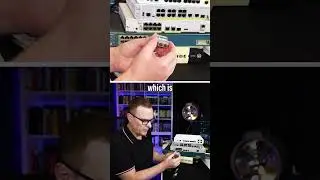
At the moment on both of these switches, a default configuration is being used.
So show spanning tree
shows us that Spanning Tree is enabled on VLAN 1.
On switch 1, all ports are forwarding, switch 1 is the root of the Spanning Tree.
Spanning Tree is also running on switch 2, on VLAN 1, the switch is not the root to switch. Interface gigabit 1/0/2 is blocking on the switch.
So let’s disable Spanning Tree
conf t no spanning-tree vlan 1
On this side no spanning-tree on vlan 1
So on switch 1 show spanning tree
shows us that Spanning Tree is disabled.
On switch 2 show spanning-tree
shows us that Spanning Tree is disabled.
Notice all ports are now showing green. No ports are being blocked.
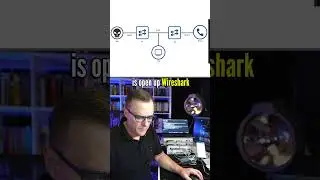
Please note that I’m running in simulation mode in packet tracer and what I’m going to do now is send a ping from PC 1 to PC 2.
PC 2’s IP address is 10.1.1.2
The MAC address of PC 2 is this.
On PC 1, IP address is 10.1.1.1 MAC address is this.
So what happens if we ping PC 2?
We’re sending an ICMP message but the PC doesn’t know the MAC address of PC 2. So it’s going to send an ARP into the network which is a broadcast and it’s going to try and find out the MAC address of PC 2. I’m going to click capture forward. The ARP message is sent to the switch. Notice what happens, it’s sent to switch 2. Switch 2 however, duplicates the packet and floods it out of all ports. So it goes back to switch 1 on gigabit 1/0/1 and it’s received by PC 2.
So PC 2 is receiving this broadcast and now PC 1 is receiving the broadcast that it’s sent. Notice the source MAC address is PC 1, destination is broadcast. It’s looking for the MAC address of PC 2. So PC 1 will drop that packet. But notice, we now have multiple packets being flooded through the network.
PC 1 has received the ARP message once again, so is PC 2.
So PC 2 is receiving multiple ARP requests from the network. The switches are also duplicating packets. When we look at the MAC address table of switch 2, we can see that PC 2 is found on gigabit 1/0/3 and PC 1 is found on gigabit 1/0/2
Capture forward notice now the switch thinks that PC 2 is connected to gigabit 1/0/2, whereas in actual fact PC 2 is connected to gigabit 1/0/3.
Once again, this is the MAC address of PC 2.
So the switch is receiving conflicting information.
Previously it thought that PC 2 is connected to this port. Now it thinks that PC 2 is connected to this port.
Capture forward again.
Now it thinks that PC 2 is connected to gigabit 1/0/1
So the switch previously thought that PC 2 is connected to 1/0/3 which is correct.
Then it thought that PC 2 is connected to 1/0/2 and now it thinks that PC 2 is connected to 1/0/1
Previously it thought that PC 1 is connected to 1/0/2, then to 1/0/1 and now to 1/0/2.
So the MAC address table is constantly being updated. This is how broadcast storms happen in live networks, which can bring down an entire network.
We have duplication of packets, we have MAC address table instability, we have hosts receiving the packets that they sent out into the network such as here PC 1 receiving its own ARP request message..........
Watch video Cisco CCNA Packet Tracer Ultimate labs: I disabled Spanning Tree! What are the Results? online, duration hours minute second in high quality that is uploaded to the channel David Bombal 23 March 2018. Share the link to the video on social media so that your subscribers and friends will also watch this video. This video clip has been viewed 7,639 times and liked it 119 visitors.