[92] Flipper Zero - Advanced SPI Topics
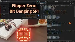
In the previous video, we learned about SPI, Serial Peripheral Interface. In this video, we learn how the external CC1101 Sub-GHz radio does async communication with the Flipper Zero. We look at how to change the speed of the external SPI bus (increasing Flipper Zero's communication with external Flash memory by 30 percent). Finally, we look at how to write an app that controls WS2812B using the MOSI pin of SPI & discuss the potential issues of communication without the SCK wire.
Previous video:
• [91] Flipper Zero - Understand SPI Pr...
Join the discord server (conversations and giveaways):
/ discord
Support the channel:
Option 1. Like, Subscribe and click the Bell (to get notified)
Option 2. https://ko-fi.com/codeallnight (donate $3 via PayPal or Venmo)
Option 3. Click the "Thanks" button on YouTube.
Lesson summary:
The CC1101 uses SPI (CS, SCK, MOSI, MISO) and GD0 to communicate with the Flipper Zero during async communication (like "Sub-GHz, Read/Read RAW").
For async Sub-GHz, GD0 contains the signal detection. MOSI/MISO contains the radio settings and RSSI values.
For sync Sub-GHz, like the CLI Chat app, the decoded data is sent on MOSI/MISO instead of GD0.
Firmware controls the speed of the SPI bus. It is typically set to furi_hal_spi_preset_1edge_low_2m, which is 2MHz SCK (using a DIV32).
We can change the speed of the bus to furi_hal_spi_preset_1edge_low_8m, which is 8MHz SCK (using a DIV8). This will increase the speed at which data is transferred from/to the Flipper Zero.
When we give the Flipper Zero data to transmit via furi_hal_spi_bus_tx(...), it does not necessarily transfer it all in one burst. It can stop sending the clock in the middle of the buffer and then resume the clock later. These gaps in the clock can be a little gap (like missing a pulse, 125 nanoseconds) to huge gaps (like 1.67milliseconds!) The protocol says the SCK is owned by the Flipper and that gaps are fine.
If we connect the MOSI pin to a Serial Input device (like the WS2812B) without also using the SCK wire, we can potentially send the signal we want (with small timing errors) or we may end up sending the entirely wrong signal (wrong values could cause damage because it could cause unexpected current draw).
Timeline:
0:00 - Introduction
0:30 - Review SPI wiring
1:03 - GD0 (async IO on CC1101)
1:32 - Preset data MOSI/MISO
1:50 - GD0 data (remote async signal)
2:08 - RSSI data MOSI/MISO (signal quality)
3:20 - External bus speed in firmware
6:10 - MOSI as Serial Output
8:00 - Danger of no SCK signal
9:00 - Summary
Watch video [92] Flipper Zero - Advanced SPI Topics online, duration hours minute second in high quality that is uploaded to the channel Derek Jamison 25 November 2023. Share the link to the video on social media so that your subscribers and friends will also watch this video. This video clip has been viewed 1,044 times and liked it 36 visitors.


