Howtomake WIFI Controlled Car Using ESP8266 || 4*4 REAL TEST ||
Howtomake WIFI Controlled Car Using ESP8266 || 4*4 REAL TEST || #diy #500subs #esp8266 mobile controlled WIFI CAR
@engineerbaccha
#HOWTOMAKE #WIFICAR #ESP8266
Hey guy's
Welcome to Engineer Baccha......................
Since childhood,
I wondered how remote control cars worked. The idea of operating a car without direct connection between the car and the remote always fascinated me. I was fortunate enough to pick ELECTRICAL ENGINEERING .
There are a lot of similar projects out there but most of them focus on either Arduino or lack proper steps and descriptions of implementation. So I wanted to write one to help my fellow enthusiasts out there. So here goes…
Hardware Requirements to make the wifi controlled car
Nodemcu ESP8266 x 1
L298N motor driver x 1
Gear motor x 4
Robot wheel x 4
Battery holder x 1
Li-ion battery x 2
Jumper wires
tags used
wifi controlled car,how to make wifi controlled car,wifi controlled robot using nodemcu,wifi controlled robot,wifi controlled car using nodemcu,wifi controlled car using esp8266,internet controlled car,esp8266 car,wifi car,diy wifi car,wifi control car,esp8266,mobile phone controlled car,node mcu wifi car,esp8266 wifi ip controlled robot,nodemcu car,wifi robot car,wifi controlled car using nodemcu and blynk application
Hey guy's
Welcome to Engineer Baccha......................
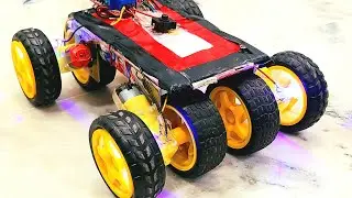
This is a wifi controlled car which u can controlled with your smartphones.
Check out How to make Mobile controlled car with using Nodemcu esp8266.
This car is ready in 1000 rupee only
Components used:
NodeMCU (esp8266) arduino
Motor Driver L298n
BO motors 200 rpm single or double shaft
[4 nos.]
BO wheels [4 nos.]
12 v battery (18650)
DC switch
Jumper wires
Motor driver pins:
Out 1: Motor A lead out
Out 2: Motor A lead out
Out 3: Motor B lead out
Out 4: Mo (Can actually be from 5v-35v, just marked as 12v)
GND: Ground
5v: 5v input (unnecessary if your power source is 7v-35v, if the power source is 7v-35v then it can act as a 5v out)
EnA: Enables PWM signal for Motor A (Please see the “Arduino Sketch Considerations” section)
In1: Enable Motor A
In2: Enable Motor A
In3: Enable Motor B
In4: Enable Motor B
EnB: Enables PWM signal for Motor B
Here's the code link :
https://drive.google.com/drive/mobile...
Code used:
https://drive.google.com/file/d/1Rmma...
Pin diagram:
https://images.app.goo.gl/kwqZUPH94RS...
Our previous vedio:
• #engineerbaccha | How To Make A DIY A...
• ENGINEER BACCHA || Promo video || #Eb
• #ArduinoProjects #ArduinoRobot #Ardui...
Follow on intagram:
@engineerbaccha
Hope u guys enjoy the vedio IF THE SUBSCRIBE ,LIKE AND SHARE THE VIDEO
Don't forget to :-
LIKE 👍
SHARE 🤳
Subscribe 👆
............ ............... 🤗 .............. ...........
My other videos .............................................links..................
1. • WOW! Amazing DIY Bluetooth Robot Car ...
2. • #ArduinoProjects #ArduinoRobot #Ardui...
3. • #engineerbaccha | How To Make A DIY A...
4. • ENGINEER BACCHA || Promo video || #Eb
Hope you all like this video,
Do you mention in the comment box..
Thanks for watching
Subscribe&support
Watch video Howtomake WIFI Controlled Car Using ESP8266 || 4*4 REAL TEST || online, duration hours minute second in high quality that is uploaded to the channel Engineer Baccha 03 September 2022. Share the link to the video on social media so that your subscribers and friends will also watch this video. This video clip has been viewed 403 times and liked it 10 visitors.